Info Microcontrollers Gebruikte Afkortingen

Info pagina ATMega328 HBO5 Elektronica

Ik zal eerst wat info over microcontrollers geven alvorens we dieper op de ATMega328 ingaan :

  • Een Harvard-architectuur is een ontwerp van CPU's dat, in tegenstelling tot de meer gebruikelijke Von Neumann-architectuur, gescheiden bussen (en adresruimtes) heeft voor data en instructies.
    Dit resulteert (over het algemeen) in een snellere processor, daar het ophalen van de volgende instructie en het wegschrijven van het resultaat van de laatste instructie gelijktijdig kan gebeuren.
    Ook wordt vaak opslagruimte uitgespaard, daar data- en instructiegeheugens niet dezelfde woordbreedte hoeven te hebben.
    In order to maximize performance and parallelism, the AVR uses a Harvard architecture
  • De Von Neumann-architectuur (ook wel bekend als het Von Neumann-model of het Princeton-architectuur) is een computerarchitectuur, die gebaseerd is op wat in 1945 door de wis- en natuurkundige John von Neumann en anderen werd beschreven in First Draft of a Report on the EDVAC.
    Dit document beschrijft een ontwerparchitectuur voor een elektronische digitale computer, waar de delen bestaan uit een centrale verwerkingseenheid (CPU), die op zijn beurt uit een rekenkundig-logische eenheid (ALU) en processorregisters bestaat, een besturingseenheid (Control Unit), bestaande uit een instructieregister en programmateller, een computergeheugen (Memory Unit) om zowel data als de instructiesets op te slaan en ten slotte externe massaopslag en input en output-mechanismen (Input en Output Devices).
    In de loop der tijd is de betekenis van een Von Neumann-architectuur geëvolueerd tot elke stored program-computer waarin het ophalen van een instructie en een bewerking op de data niet op hetzelfde moment kunnen plaatsvinden, dit omdat zij een gezamenlijke bus delen. Dit wordt wel aangeduid als de Von Neumann-flessenhals en is vaak een beperkende factor in de prestaties van een computersysteem.
  • 8 -16 -32 bit? 32 bit ? Dit is de breedte van de databus , hoeveel bytes in 1 klok verwerkt kunnen worden
  • Wat zijn registers ? In computer architecture, a processor register is a quickly accessible location available to a digital processor's Central Processing Unit (CPU). Registers usually consist of a small amount of fast storage, although some registers have specific hardware functions, and may be read-only or write-only. Registers are typically addressed by mechanisms other than main memory, but may in some cases be memory mapped.
    Among of the some Mostly used Registers named as AC or Accumulator, Data Register or DR, the AR or Address Register, program counter(PC), Memory Data Register (MDR) ,Index register,Memory Buffer Register.
Navigeren in de ATMega328 datasheet.
Grondige berschrijving (datasheet) van de ATMega328.
Omschrijving registers
ATmel heeft zelf een cursus programmeren ontworpen.
En we hebben ook nog een cursus C++

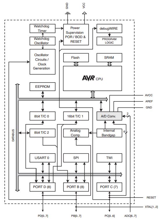
De ATMega328 is een 8-bit microcontroller met 32K flash , 2K ram geheugen en draait op 16 MHz.


Als je zoekt naar het bestand "iom328p.h" bij Dependencies kan je zien welke registers beschikbaar zijn in je software

GPIO (General Purpose IO)

De Arduino Uno is een bord gebaseerd op de ATmega328 chip. Deze Uno heeft 14 digitale input / output pinnen (waarvan er 6 gebruikt kunnen worden als PWM outputs), 6 analoge inputs.
Elke pin kan 20 mA leveren of ontvangen en heeft een interne pull-up weerstand (default ontkoppeld) van 20-50k ohm.
Sommige pinnen hebben een speciale functie :
  • Serial: 0 (RX) and 1 (TX). Used to receive (RX) and transmit (TX) TTL serial data.
    These pins are connected to the corresponding pins of the ATmega8U2 USB-to-TTL Serial chip.
  • External Interrupts: 2 and 3. These pins can be configured to trigger an interrupt on a low value, a rising or falling edge, or a change in value.
  • PWM: 3, 5, 6, 9, 10, and 11. Provide 8-bit PWM output with the analogWrite() function.
  • SPI: 10 (SS), 11 (MOSI), 12 (MISO), 13 (SCK). These pins support SPI communication using the SPI library.
  • LED: 13. There is a built-in LED driven by digital pin 13. When the pin is HIGH value, the LED is on, when the pin is LOW, it's off.
  • TWI: A4 or SDA pin and A5 or SCL pin. Support TWI communication using the Wire library.
  • The Uno has 6 analog inputs, labeled A0 through A5, each of which provide 10 bits of resolution (i.e. 1024 different values).
    By default they measure from ground to 5 volts, though is it possible to change the upper end of their range using the AREF pin and the analogReference() function.
  • There are a couple of other pins on the board:
  • AREF. Reference voltage for the analog inputs. Used with analogReference().
  • Reset. Bring this line LOW to reset the microcontroller. Typically used to add a reset button to shields which block the one on the board.

Pin-mapping :

  • pin Digital 0 = PORT_D 0 = USART RX
  • pin Digital 1 = PORT_D 1 = USART Tx
  • pin Digital 2 = PORT_D 2 = Ext Int 0
  • pin Digital 3 = PORT_D 3 = PWM T2_B , EXT Int 1
  • pin Digital 4 = PORT_D 4 =
  • pin Digital 5 = PORT_D 5 = PWM T0_B
  • pin Digital 6 = PORT_D 6 = PWM T0_A
  • pin Digital 7 = PORT_D 7 =
  • pin Digital 8 = Port B 0 = Input Capture
  • pin Digital 9 = Port B 1 = PWM T1_A
  • pin Digital 10 = Port B 2 = PWM T1_B , SS
  • pin Digital 11 = Port B 3 = PWM T2_A , MOSI
  • pin Digital 12 = Port B 4 = MISO
  • pin Digital 13 = Port B 5 = SCK
  • pin Analog 0 = PORT C 0 =
  • pin Analog 1 = PORT C 1 =
  • pin Analog 2 = PORT C 2 =
  • pin Analog 3 = PORT C 3 =
  • pin Analog 4 = PORT C 4 = I2C SDA
  • pin Analog 5 = PORT C 5 = I2C SCL
PORTD maps to Arduino digital pins 0 to 7
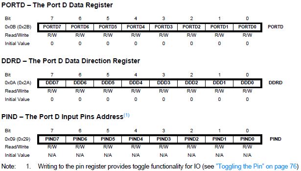
DDRD - The Port D Data Direction Register - read/write (default 0x00, as input configured)
PORTD - The Port D Data Register - read/write
PIND - The Port D Input Pins Register - read only


Toggling the Pin :
Writing a logic one to PINxn toggles the value of PORTxn, independent on the value of DDRxn.
Note that the SBI instruction can be used to toggle one single bit in a port.

PORTB maps to Arduino digital pins 8 to 13 The two high bits (6 & 7) map to the crystal pins and are not usable
DDRB - The Port B Data Direction Register - read/write
PORTB - The Port B Data Register - read/write
PINB - The Port B Input Pins Register - read only

PORTC maps to Arduino analog pins 0 to 5. Pins 6 & 7 are only accessible on the Arduino Mini
DDRC - The Port C Data Direction Register - read/write
PORTC - The Port C Data Register - read/write
PINC - The Port C Input Pins Register - read only

DDRD = 0b11111111; All pins in PORTD are outputs
PORTD = 0b11111111; All pins in PORTD are high
PORTD = 0b00000000; All pins in PORTD are low
PORTD = 0b10101010; The small on,off,on,.. pattern

DDRD = 0b00000000; All pins in PORTD are inputs
char my_var = 0; Create a variable to store the data read from PORTD
my_var = PIND; Read the PORTD and put the values in the variable

DDRD = (1< PORTD = (1<
DDRD = 0b11111101; Pin 1 of PORTD is an input, all others are outputs
char my_var = 0; Create a variable to store the data read from PORTD
my_var = (PIND & (1<
DDRD = 0b11111100; Portd pins 0 and 1 are inputs, all the others are outputs
if(PIND & ((1< Code inside the if() statement will be executed when both buttons are high
}

DDRD &= ~(1< PORTD |= (1< DDRB |= (1< if((PIND & (1< PORTB ^=(1<

U(S)ART (Seriele communicatie)

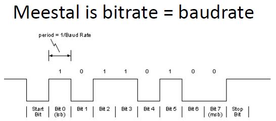
De breedte van het ontvangen (te versturen) pakket is afhankelijk van :
- Start bit
- Data byte (5, 6, 7, 8 of 9 bits)
- Stop bit (1 of 2 bits)
- Parity bit (optioneel)


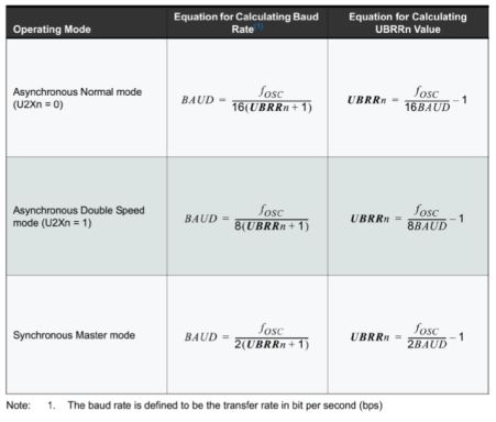
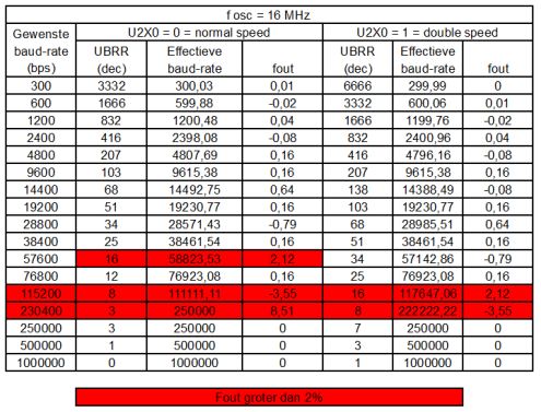
UBRR0 = UBRR0 = Uart Baud Rate Register voor UART0

- Arduino : Serial.begin(9600); - C : waarde opzoeken of berekenen : UBRR0 = 103;
- UBRR0H = 0;
- UBRR0L = 103;

void loop()
{
Serial.begin(9600); // ik wijzig deze waarde telkens om te testen
// Deze Serial.begin rekent uit welke waarde hij in de registers UBRR0L en UBRR0H moet stoppen
// Omdat dit 2 bytes zijn moeten we ze afzonderlijk naar de UART (UDR0) sturen
// We moeten natuurlijk hierbij ook weten of de UART op normal of double speed staat
char_U2X0_waarde=U2X0;
if (char_U2X0_waarde == 0)
{
USART_SendStringLF(Txt_Normal_Speed);
}
else
{
USART_SendStringLF(Txt_Double_Speed);
}
USART_SendStringLF(Txt_UBRR0L_waarde);
UBRR0x_waarde=UBRR0L;
USART_SendByte(UBRR0x_waarde);
USART_SendByte(LF);

USART_SendStringLF(Txt_UBRR0H_waarde);
UBRR0x_waarde=UBRR0H;
USART_SendByte(UBRR0x_waarde);
USART_SendByte(LF);
}

Afkortingen

  1. AVR: Advanced Virtual Risc = Geavanceerde virtuele RISC
  2. Flash = Niet-vluchtig (non-volatile) solid state (geen mechanische onderdelen) geheugen kan data bewaren zonder dat er een spanningsbron nodig is om het geheugen blijvend te voeden.
  3. IDE = Integrated Development Environment
  4. ISP = In-System Programming , program the controller without removing from socket
  5. RAM = Random Access Memory , geheugen met willekeurige toegang, is een computergeheugen, waarvan iedere geheugenplaats even snel toegankelijk is (in tegenstelling tot bijvoorbeeld een harde schijf waarbij gewacht moet worden tot de betreffende plek onder de leeskop doordraait). Ook kan bij RAM in willekeurige (random) volgorde data uit het geheugen gelezen worden of data geschreven worden in het geheugen
  6. ROM = Read Only Memory
  7. UART = Universal Asynchronous Receiver Transmitter , from the name itself, it is clear that it is asynchronous i.e. the data bits are not synchronized with the clock pulses.
  8. UBRR = Usart Baud Rate Register
  9. USART = Universal Synchronous Asynchronous Receiver Transmitter , this is of the synchronous type, i.e. the data bits are synchronized with the clock pulses.


Ga in Amel Studio naar Tools -external tools
Vul het het venster datje ziet in met deze gegevens :
• Naam van je tool ( Bv 'Arduino on COM5)
• Pad naar 'avrdude.exe' (C: 'avrdude.exe' (C:\Program Files(x86)\Arduino\hardware\tools\avr\bin\avrdude.exe)
• -C"C:\Program Files (x86)\Arduino\hardware\tools\avr\etc\avrdude.conf" -v -patmega328p -carduino -PCOM4 -b115200 -D -Uflash:w :"$(ProjectDir)Debug \$(TargetName).hex":i